Vision-Guided Robotic Arm
A 5-DOF arm that finds the object instead of being told where it is.
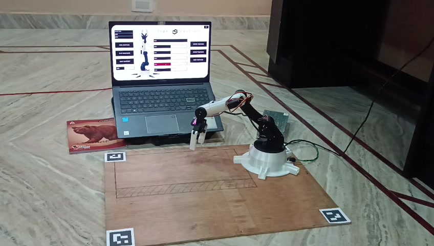
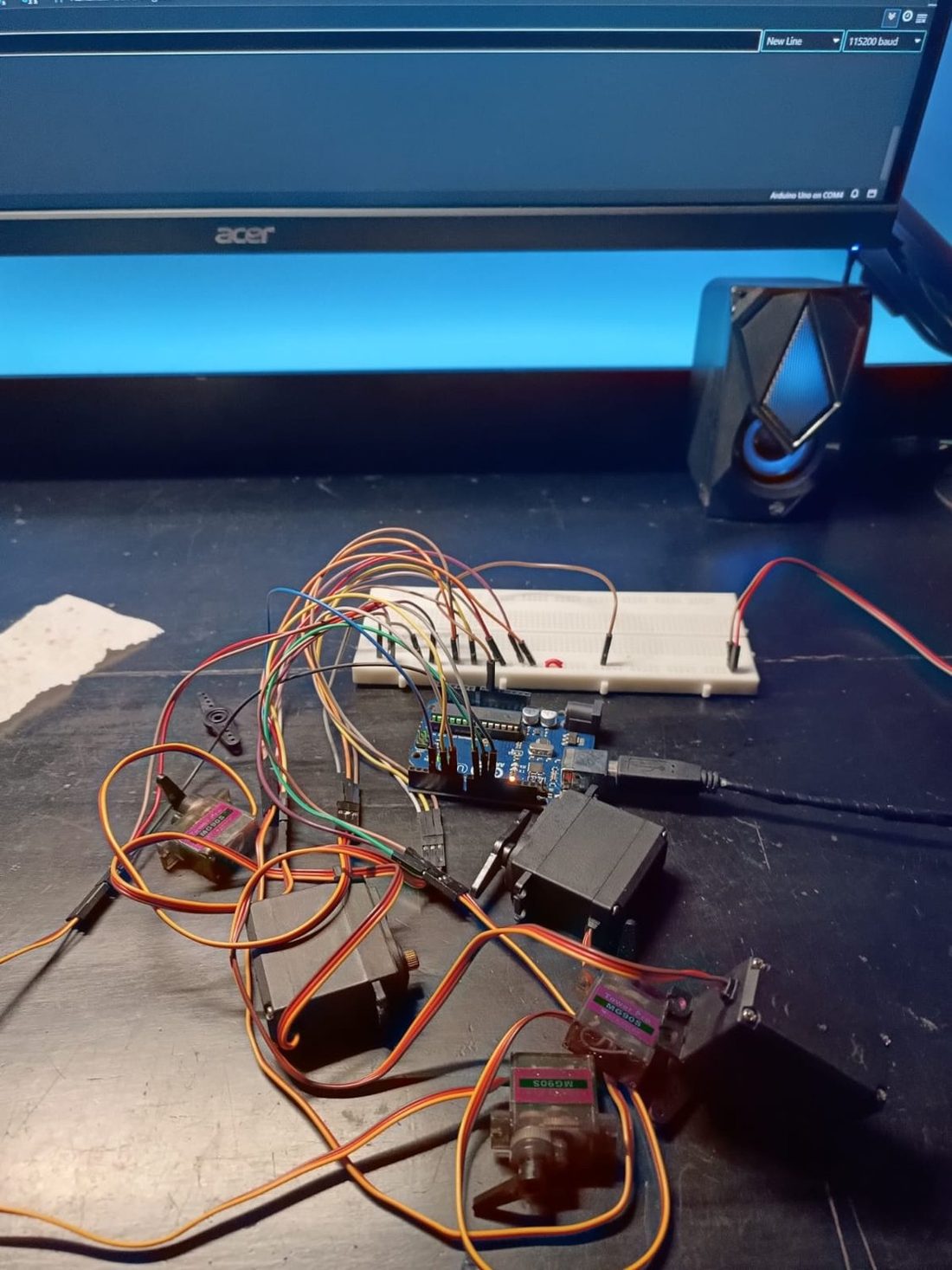
The camera does not measure position. It measures pixels. Everything downstream depends on turning those into millimetres correctly.
Overview
A desktop arm that finds objects with an overhead camera and picks them up. The camera spots ArUco-tagged objects, a custom inverse-kinematics solver works out the joint angles to reach them, and an Arduino drives six servos through a smooth pick-and-place sequence.
Problem
Most low-cost arms are told where the object is. This one has to work it out.
System
An overhead camera detects ArUco markers and calibrates the workspace from four corner tags, perspective-warping the view into real-world millimetres. A custom inverse-kinematics solver converts a target into six joint angles, and a serial protocol streams them to Arduino firmware driving the servos through a PCA9685.
How it works
- A phone camera streams frames to the laptop over Wi-Fi.
- Four corner markers (IDs 1-4) calibrate the workspace, and the view is perspective-warped into real-world millimetres.
- Each object's ArUco tag gives its position in the workspace.
- The IK solver turns that position into five joint angles plus the gripper, keeps the gripper parallel to the ground, and checks the target is reachable before anything moves.
- The laptop sends the angles over serial as a short ASCII command, and the Arduino moves every servo smoothly to them through the PCA9685.
- The sequence runs approach, lower, grip, lift, move, drop and retract, with a priority order when several objects are present.
Hardware
| Part | What it does |
|---|---|
| Arduino Uno | Servo controller |
| PCA9685 | 16-channel PWM driver |
| 6 servos | Base, shoulder, elbow, wrist, wrist rotate, gripper |
| Phone camera | Overhead IP webcam over Wi-Fi |
| 2 × 18650 + buck converter | About 6 V for the servos |
| ArUco markers | Four corners and the object tags |
Software
- Python with OpenCV, NumPy and pySerial on the laptop: vision, calibration, IK and the serial layer.
- Split into modules (configuration, IK solver, camera system, Arduino interface, a diagnostic tool) as well as one all-in-one script.
- Arduino firmware with interpolated servo motion, answering H, A, M, S, STOP and STATUS at 115200 baud.
My part
I built the vision pipeline, the coordinate mapping, the IK solver and the host control layer, then led the four-person team and integrated vision, kinematics and firmware into one system.
Challenges
Pixels are not millimetres
The camera only reports pixels, so everything depends on the four-corner calibration and the warp being right before a single angle is solved.
A gripper that stays level
Keeping the gripper parallel to the ground fixes one degree of freedom and makes the reach predictable, and every target is checked before the arm moves.
A lost file
The original camera module was lost to file corruption. It was rebuilt from the identical class that also lives in the all-in-one script, so its behaviour is unchanged.
Result
Executes the full approach, grip, lift, move and release sequence. Positioning accuracy is still being calibrated and it does not yet complete a pick reliably. The IK model and several hardware constraints remain open.
What's next
- Calibrate positioning until picks are reliable.
- Relax the planar-wrist assumption in the IK.