An IRF540 wants about 10 V on the gate and the ESP32 gives 3.3 V. The wrong part sits half-on, drops voltage across itself and runs hot.
Overview
A hand-built ESP32 controller that drives about 400 addressable WS2812B LEDs under WLED, with a MOSFET output stage so the same board also drives analog RGB strips. Wi-Fi and app control, and screen sync from the PC through SignalRGB.
Problem
Addressable strips have a controller chip. Analog strips do not. Driving both from one board needs an output stage.
System
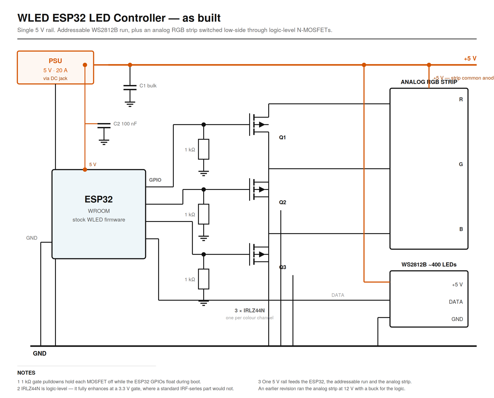
An ESP32 running WLED handles roughly 400 addressable LEDs directly. Three logic-level MOSFETs switch the analog strip low-side: common anode to the rail, each colour returning to ground through its transistor.
How it works
- The ESP32 runs stock WLED, flashed with the web installer, and the addressable strip is set up in WLED's LED settings.
- Analog strips have no controller chip, so three IRLZ44N MOSFETs switch them: the common anode on +5 V and each colour's cathode to ground through its own MOSFET, PWM from the ESP32.
- 1 kΩ pulldowns hold each gate at 0 V until WLED has started, so the strip can't flash or latch on at power-up.
- SignalRGB on the PC captures the screen and syncs the colours over Wi-Fi.
Hardware
| Part | What it does |
|---|---|
| ESP32-WROOM | Runs WLED |
| ≈ 400 WS2812B | Addressable strip |
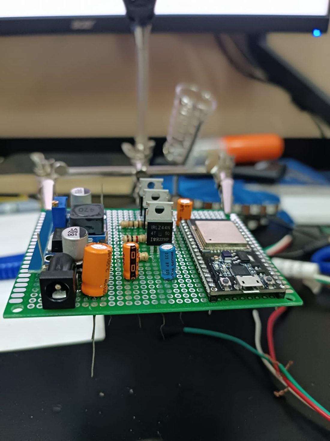
| 3 × IRLZ44N | Logic-level output stage |
| 3 × 1 kΩ | Gate pulldowns |
| 5 V 20 A supply | One rail for everything |
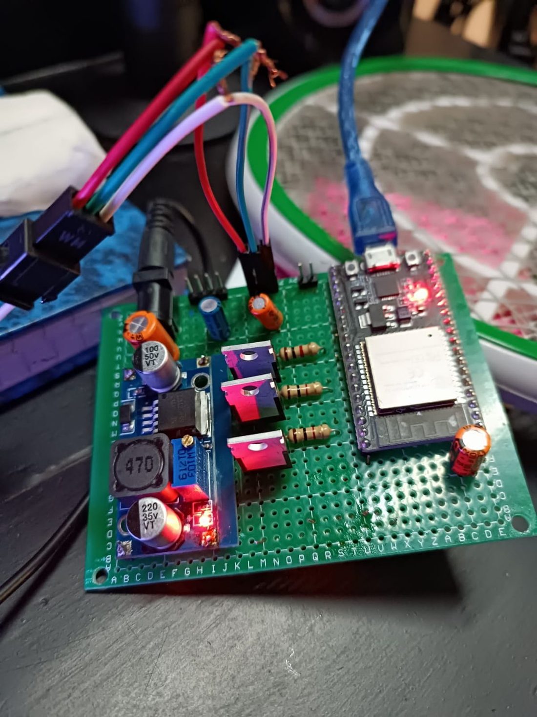
| Protoboard | Hand-soldered |
Software
- Stock open-source WLED. I wrote none of the firmware; the engineering here is the hardware.
- The analog channels mapped to the ESP32 PWM pins that drive the MOSFET gates.
- SignalRGB for screen capture and sync on the PC.
My part
The build, the output stage and the power design are mine. The firmware is stock open-source WLED, so my part here is the hardware.
Challenges
The wrong MOSFET runs hot
An IRF540 wants about 10 V on its gate and the ESP32 gives 3.3 V. It would sit half-on, drop voltage across itself and give dim, uneven colour. The IRLZ44N turns fully on at logic level.
Sizing the supply
400 LEDs at full white would pull about 24 A, more than the 20 A supply. Ambient lighting never sits there, and WLED's brightness limit holds the ceiling.
One rail, not two
The first version ran the analog strip at 12 V with a buck converter for the logic. Moving to 5 V strips removed the 12 V rail and the converter.
Result
Halfway through I swapped the 12 V strips for 5 V ones. That removed the second supply rail and the buck converter, and the board got simpler for it.